-
Combined Cycle Power Plant
Piping Design and Analysis for High Energy Indian Boilers Regulations (IBR) lines, Pipe support engineering, 3D design for the complete plant and generation of GA drawings, IBR and Non-IBR isometrics with BOM, Support detailed drawings and reports from the 3D model for a 180 MWe Combined Cycle Power Plant
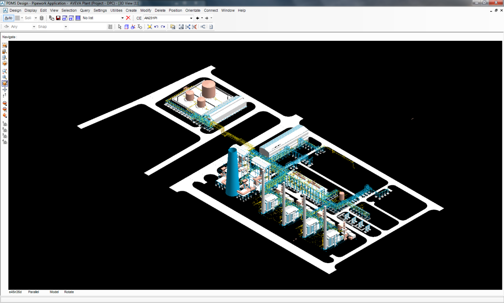
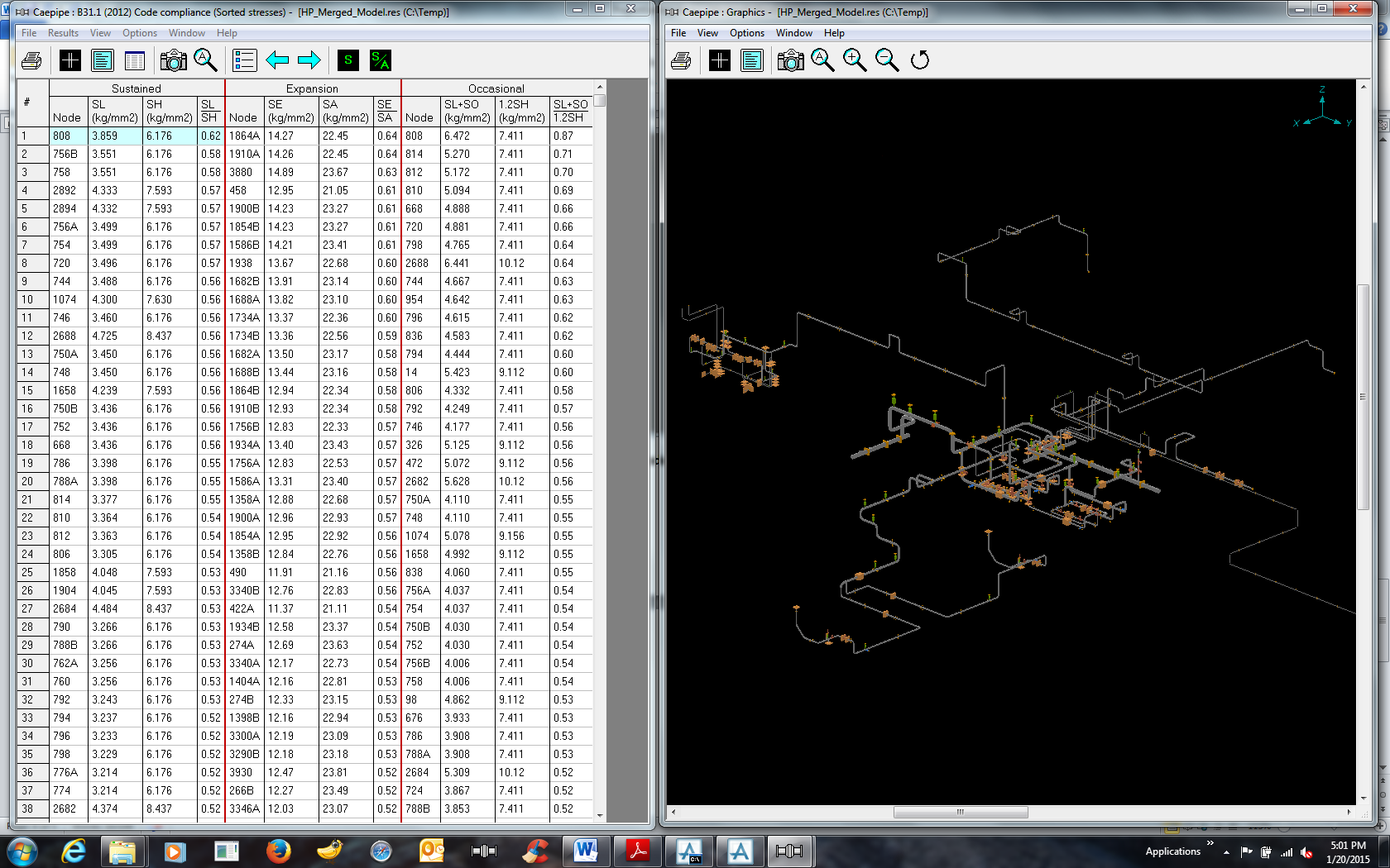
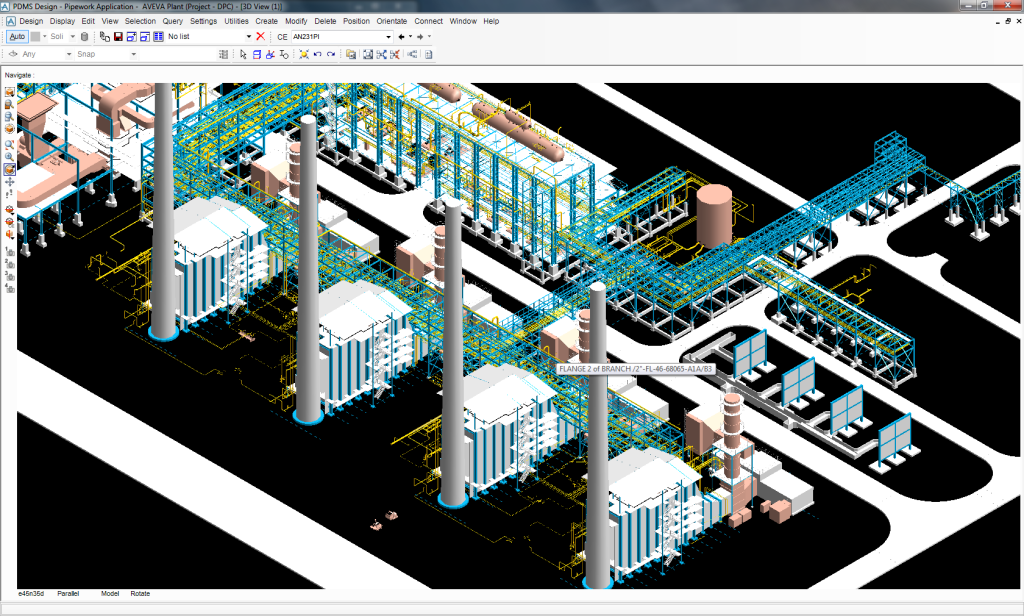
ISO view of the 180 MWe Combined Cycle Power Plant
Closer view of the Heat Recovery Steam Generator Area
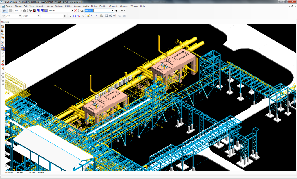
Closer view of Utility Boiler Area
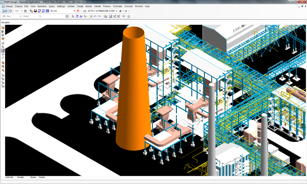
Closer view of Steam Turbine Generator Building with TG deck

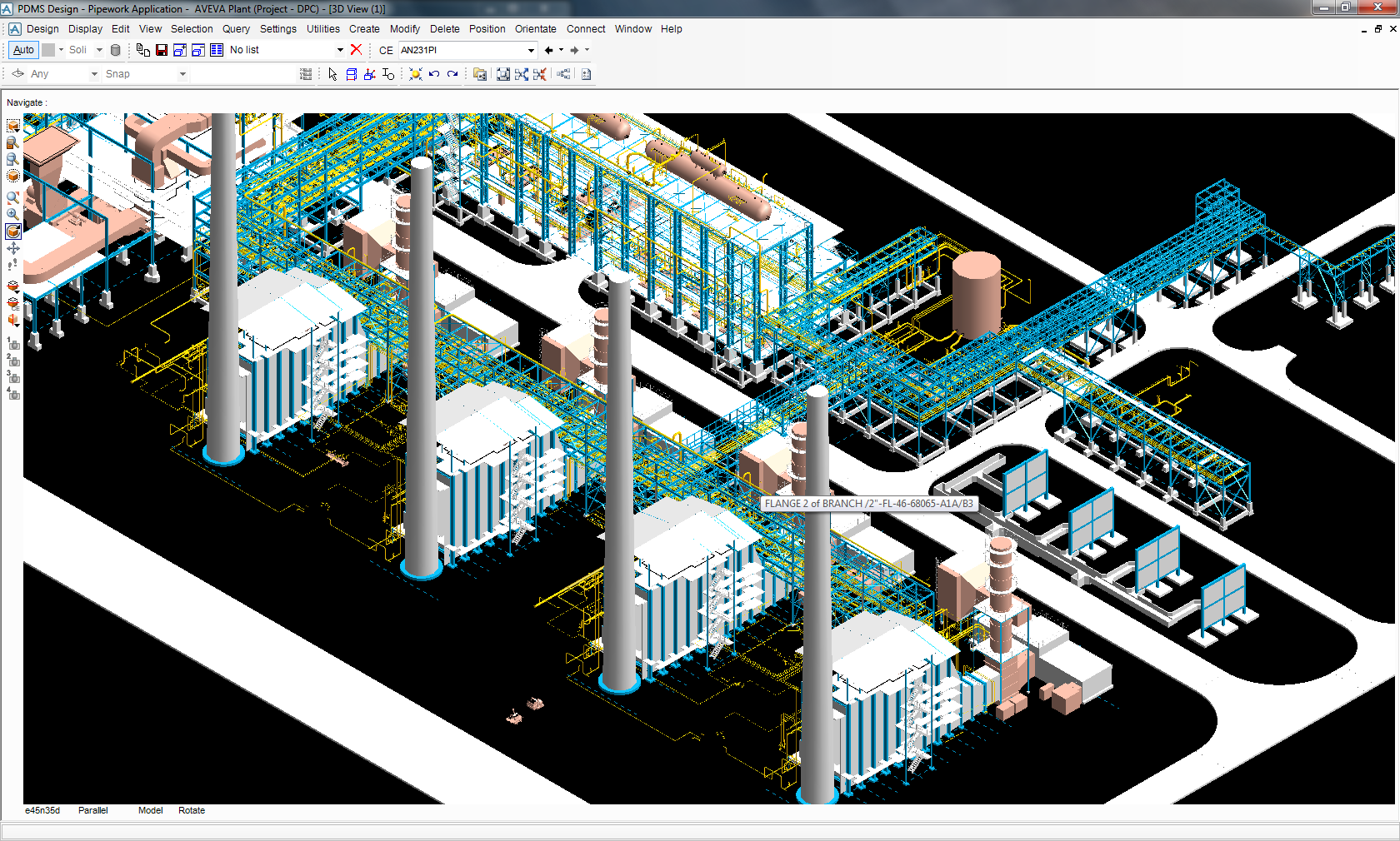
Pipe Rack with IBR and Non-IBR Piping
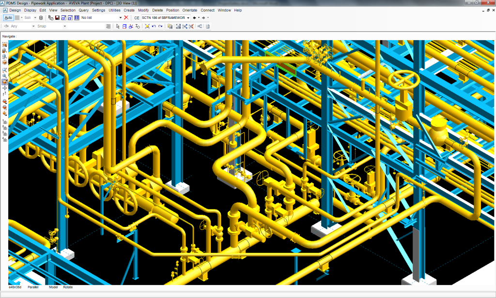
High Energy Large Diameter IBR Piping with Supports
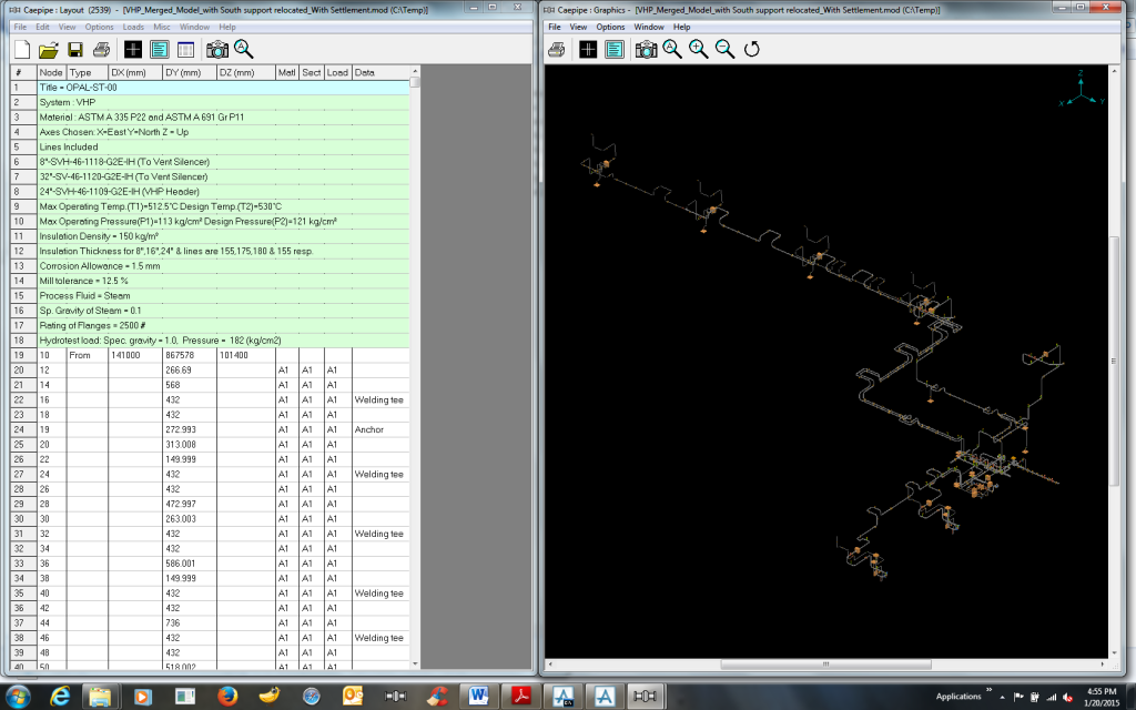
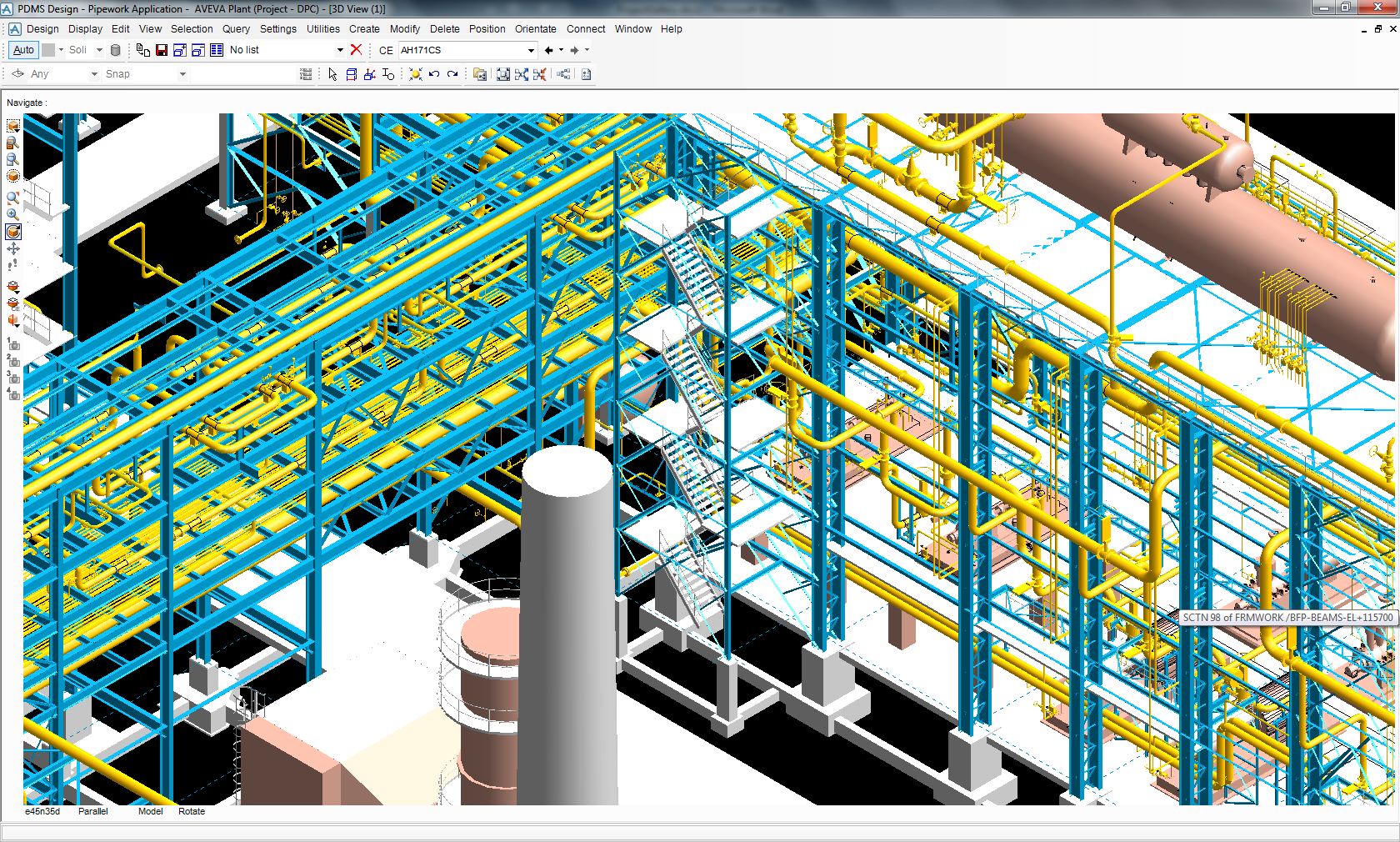
CAEPIPE Stress Model for Very High Pressure (VHP) System
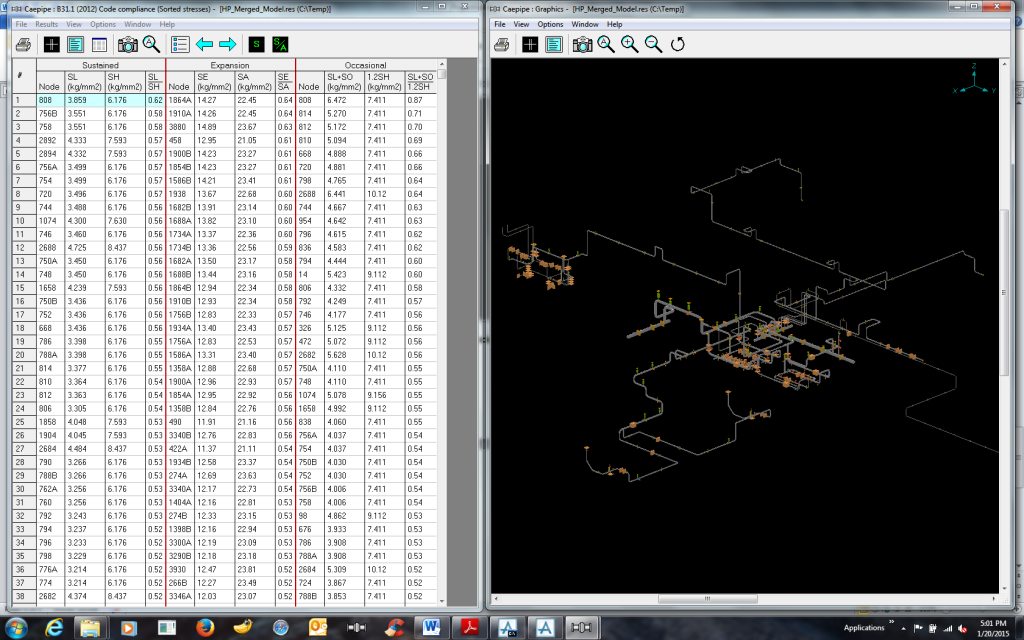
B31.1 (2012) Code Compliance (Sorted Stresses) for High Pressure (HP) System
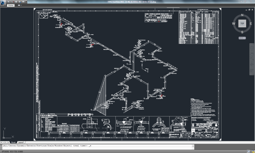
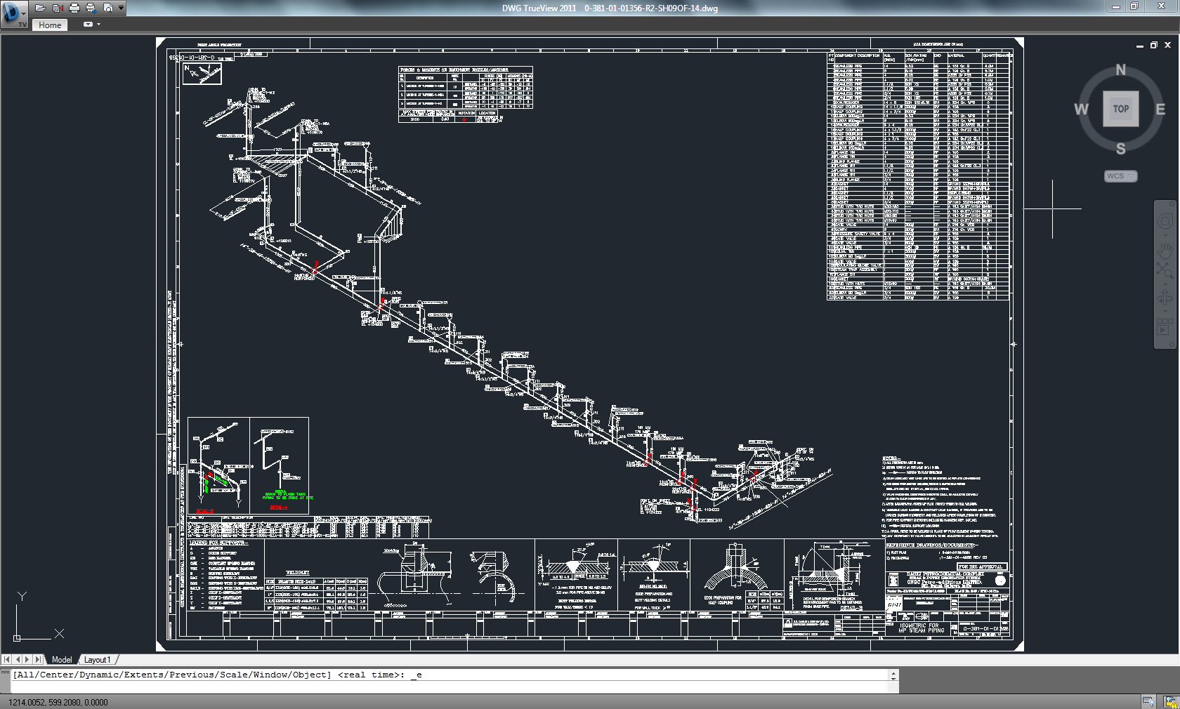
Customized IBR Isometrics for VHP System using 3D Plant Design software

Customized IBR Isometrics for Medium Pressure (MP) System using 3D Plant Design software
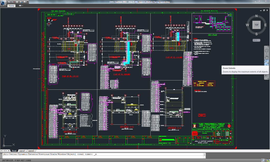
Area Wise – Support Marked Piping Layout using 3D Plant Design software
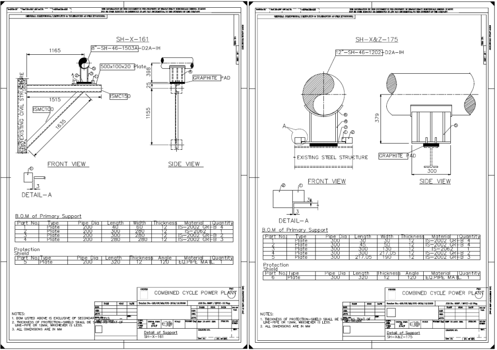
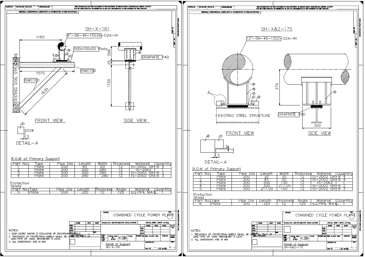
Customized Support Detailed Drawings using 3D Plant Design software
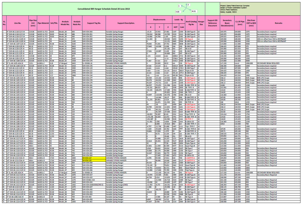
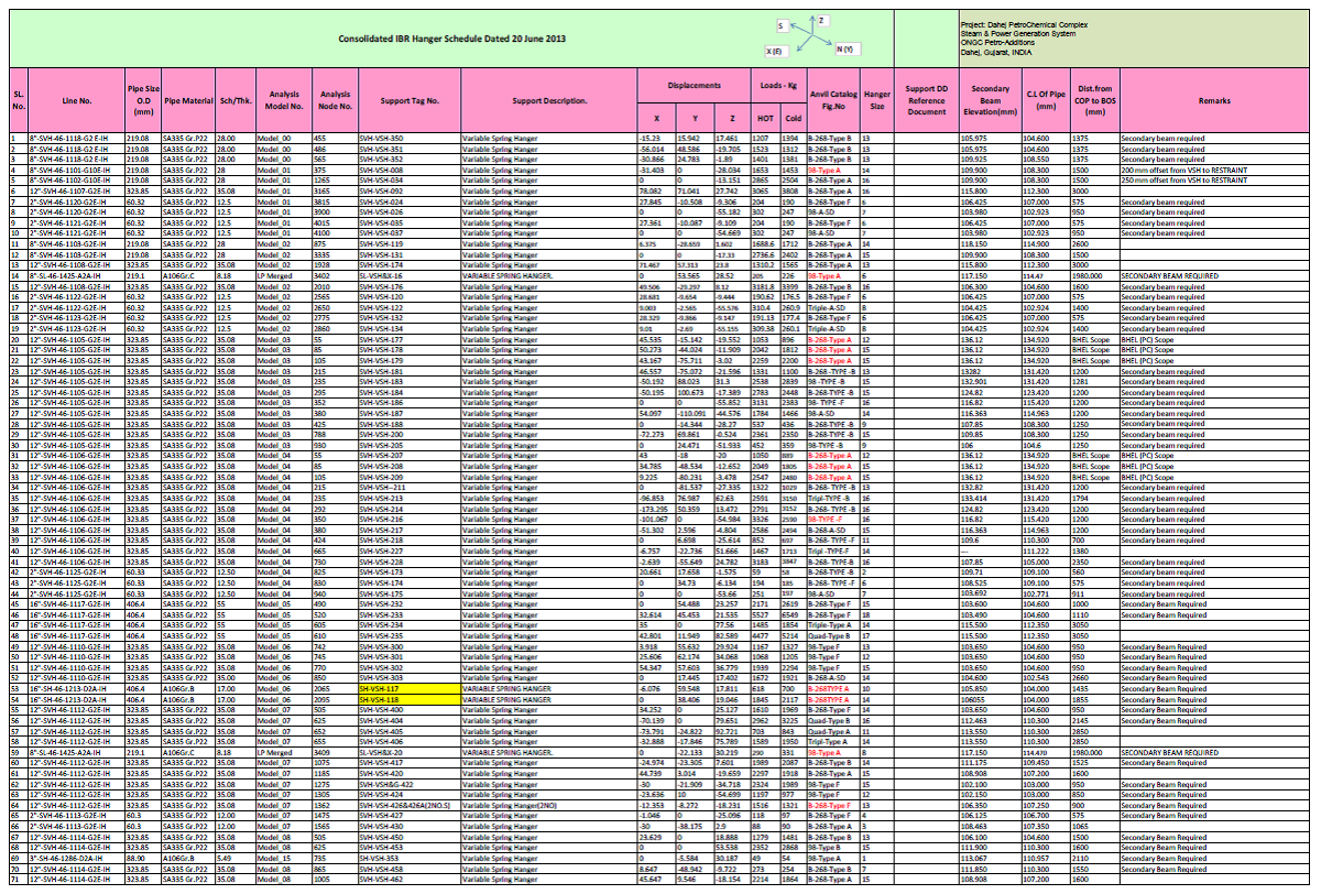
Consolidated IBR Hanger Schedule
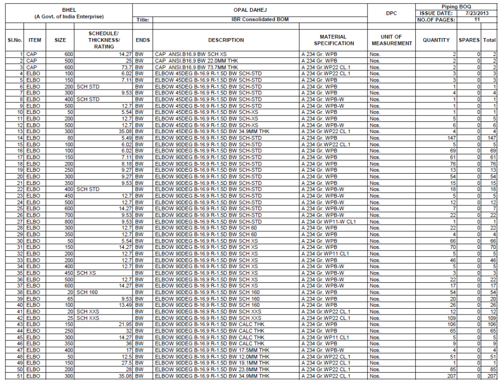
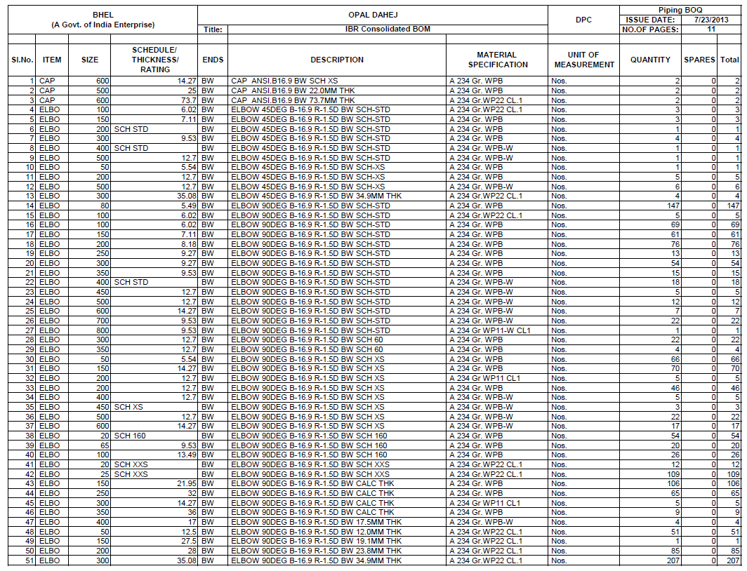
Bill of Quantities for IBR Piping
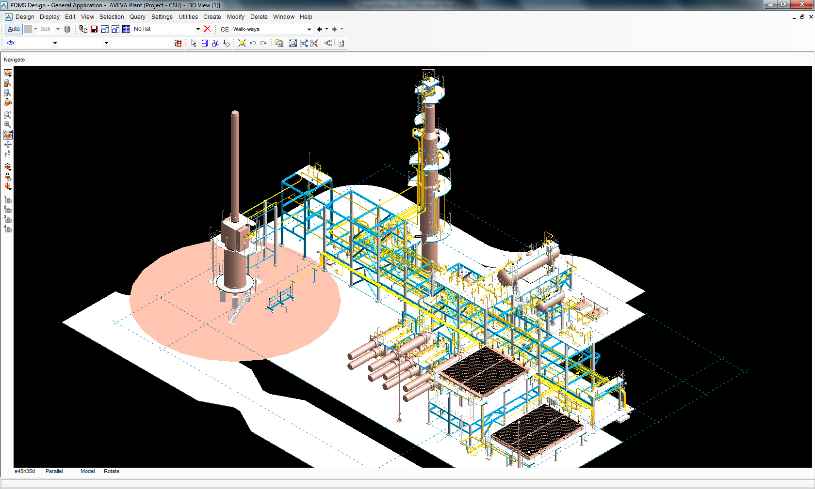
Crude Stabilization Unit at an Oil field
Design and engineering involving piping design, layout in 3D, piping analyses, pipe support design and generation of GA drawings, isometrics and MTO from 3D plant model for the Crude Stabilization Unit.

ISO view of the Crude Stabilization Unit
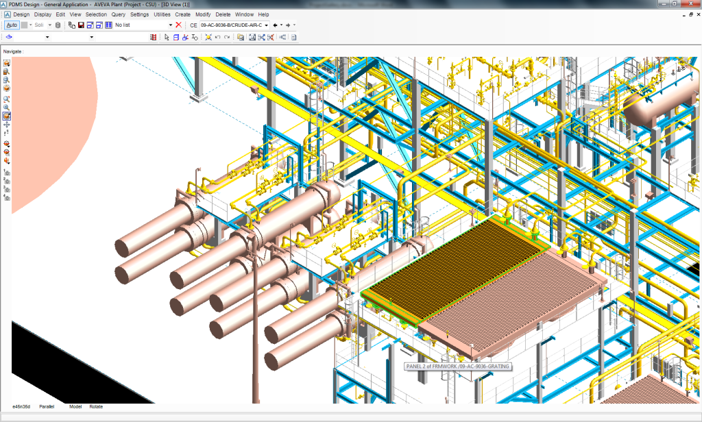
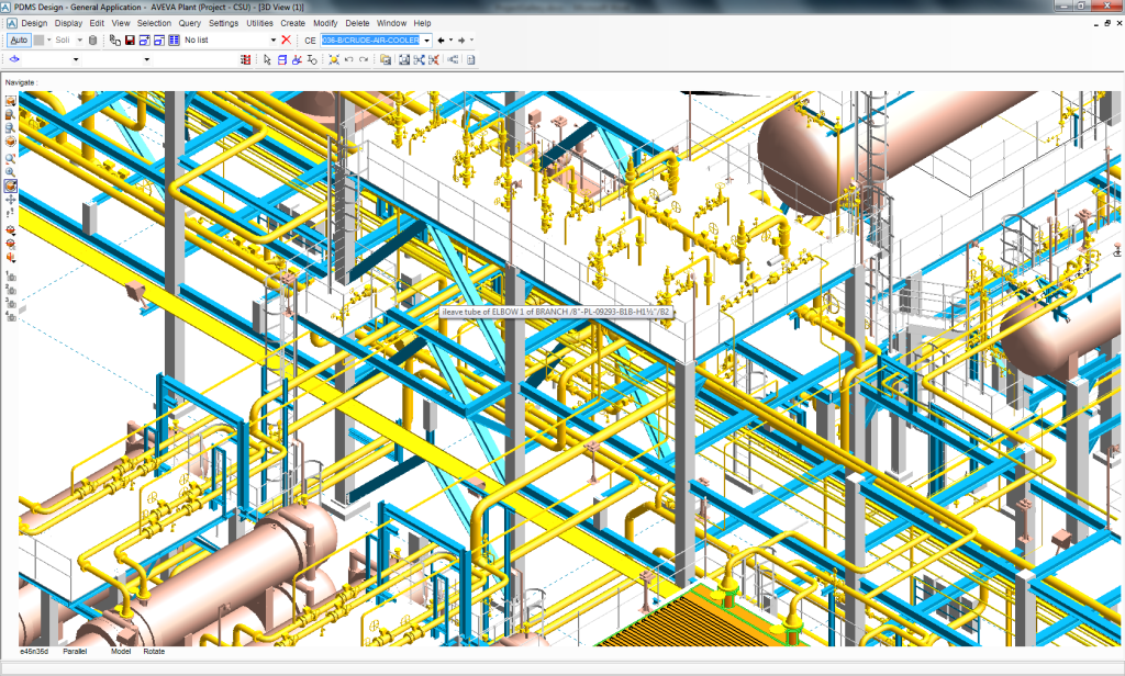
Closer view of the Heat Exchanger and Crude Air Cooler
Closer view of the Pipe Rack with Piping Layout

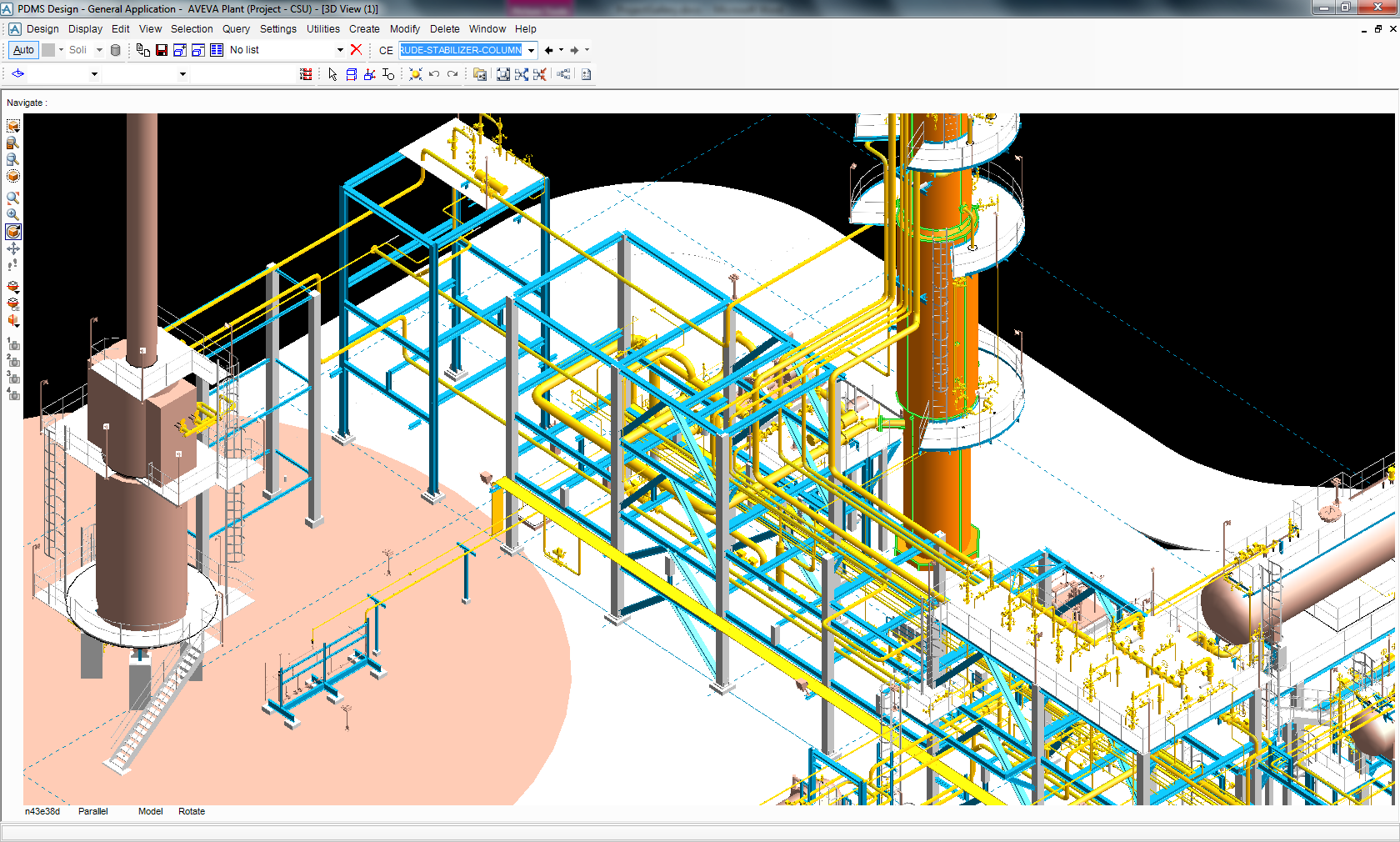
Closer view of the Crude Stabilizer Column with associated Piping
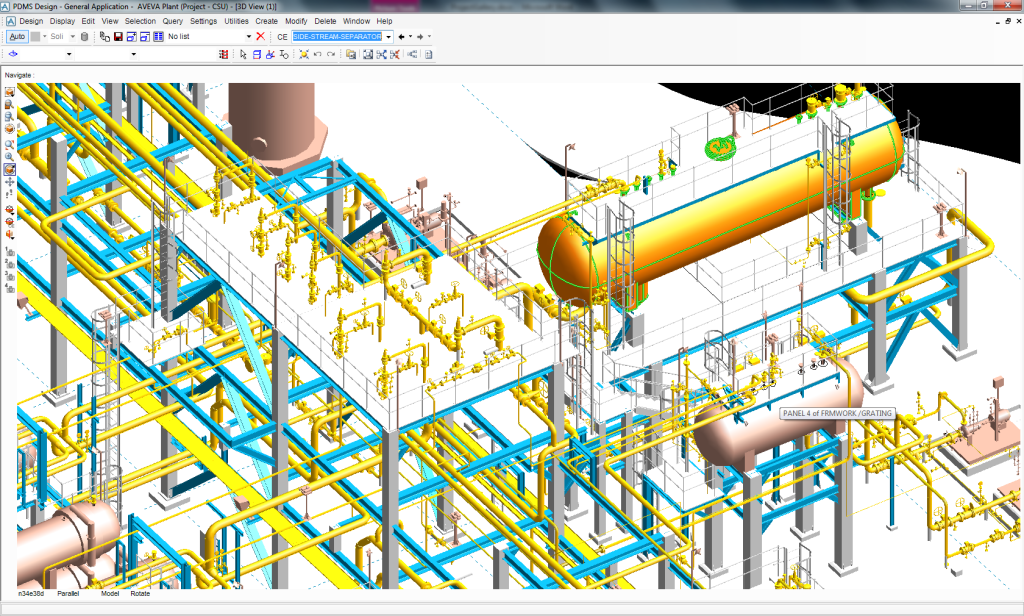
Closer view of the Side Stream Separator with associated Piping
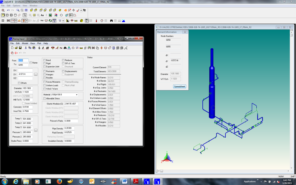
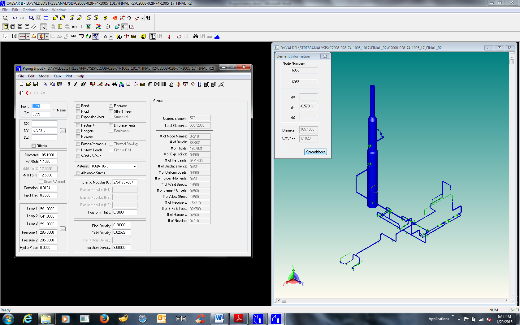
Stress Analysis of the Piping using CAESAR II
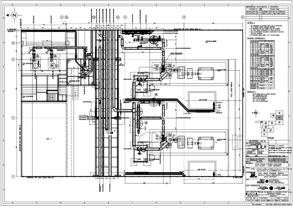
Customized GA Drawing produced using 3D Plant Design software
Customized Isometrics with BOM produced using 3D Plant Design software
Tank Farm for a Chlorine Dioxide Plant
Routing of pipelines including selection and location of pipe supports and development of 3D model using PDMS Global for the Tank Farm area and detailing of pipe supports.
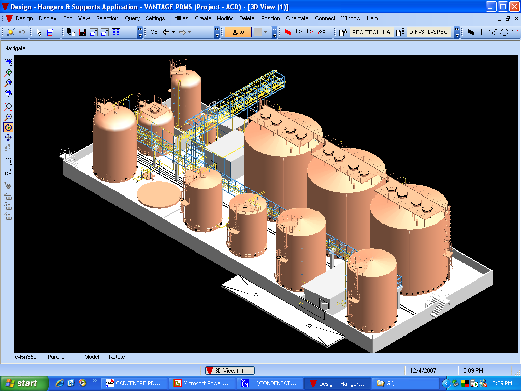
ISO view of the Tank Farm Layout
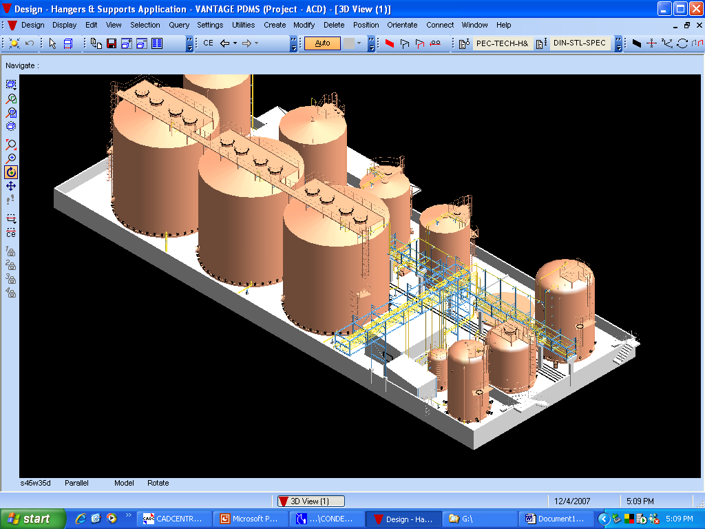
ISO view of the Tank Farm Layout
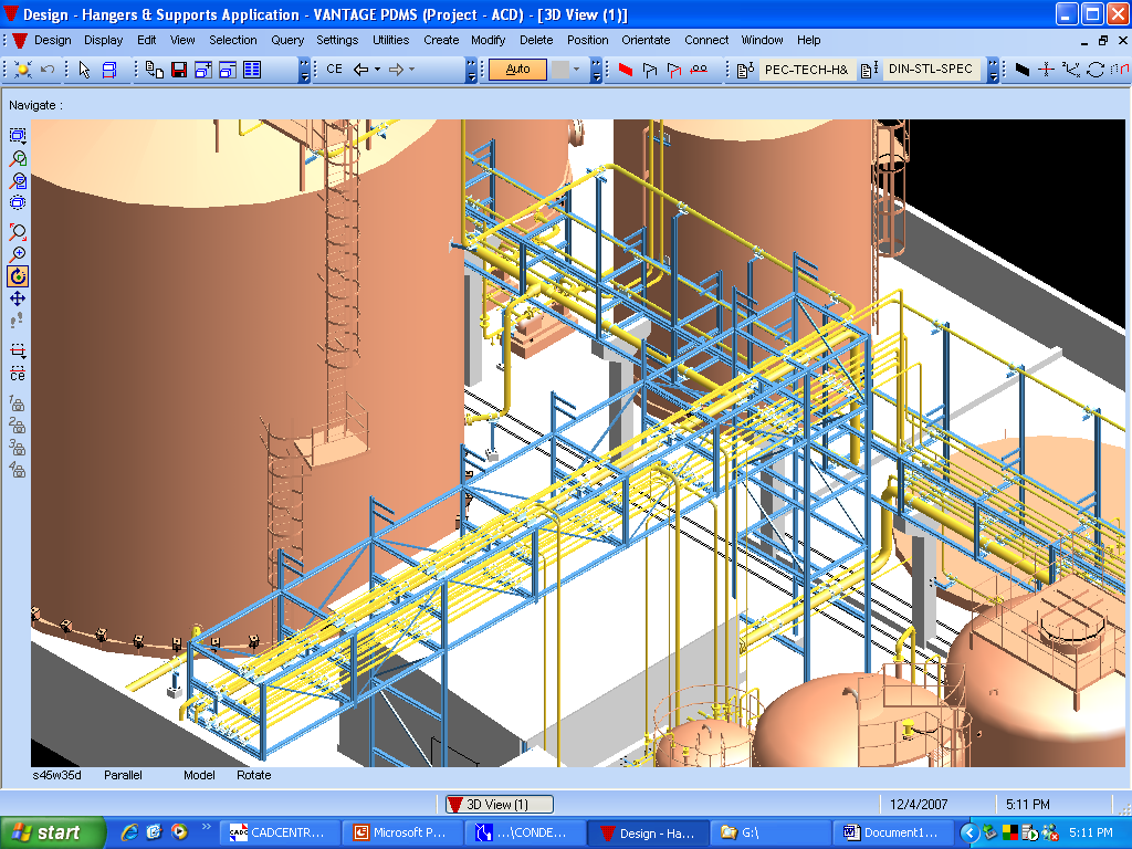
Closer view of the Tank Farm Area

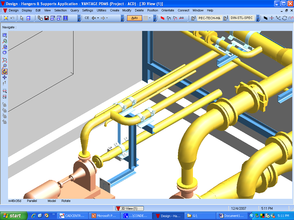
Large Diameter Piping with Secondary Support Design & Layout

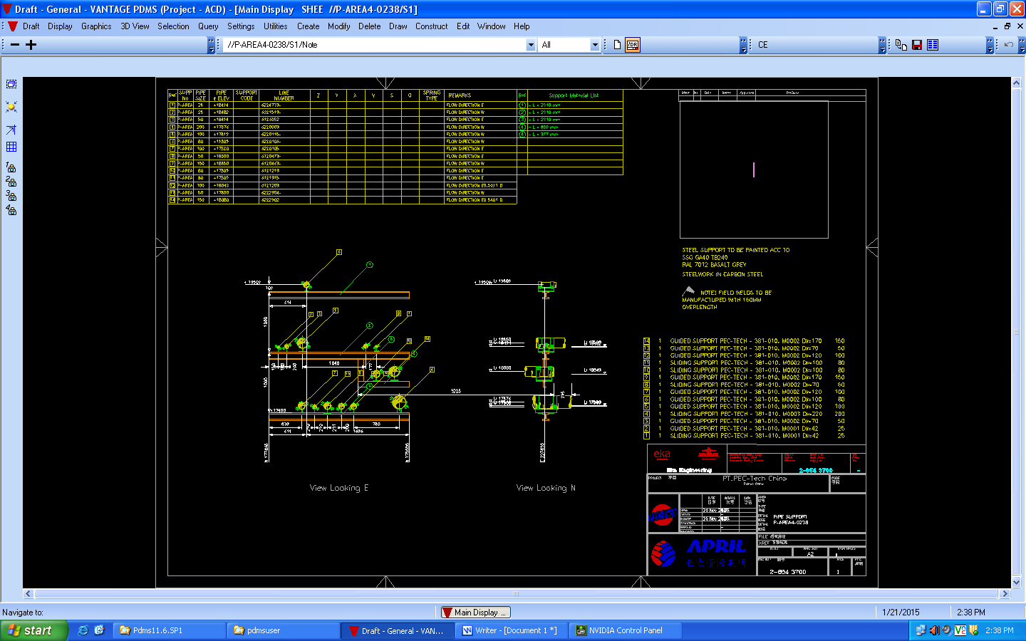
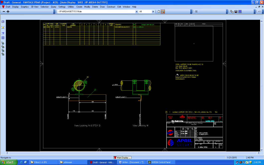
Support Detailed Drawing produced using 3D Plant Design software
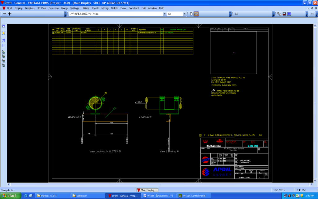
Support Detailed Drawing produced using 3D Plant Design software
Tank Farm for a Waste Water Treatment Plant
Development of piping layout drawings (plan and sections) and generation of isometrics (with BOM) involving 28 P&IDs (by Bayer Technologies) for a Tank farm area with over 500 pipelines of CS, SS and Polypropylene materials
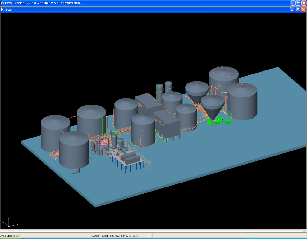
ISO view of Tank Farm Area
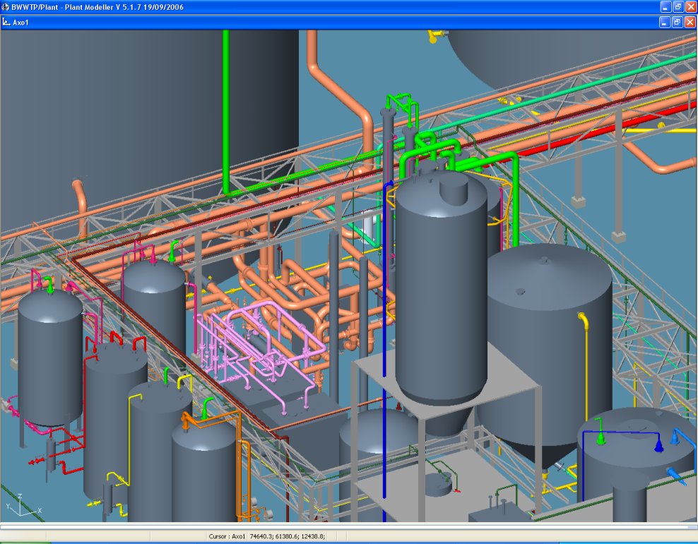
Closer view of Tank Farm Area Piping
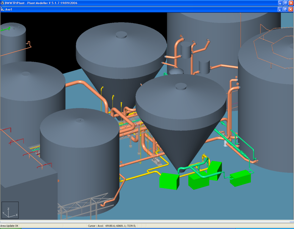
Closer view of Tank Farm Area Piping
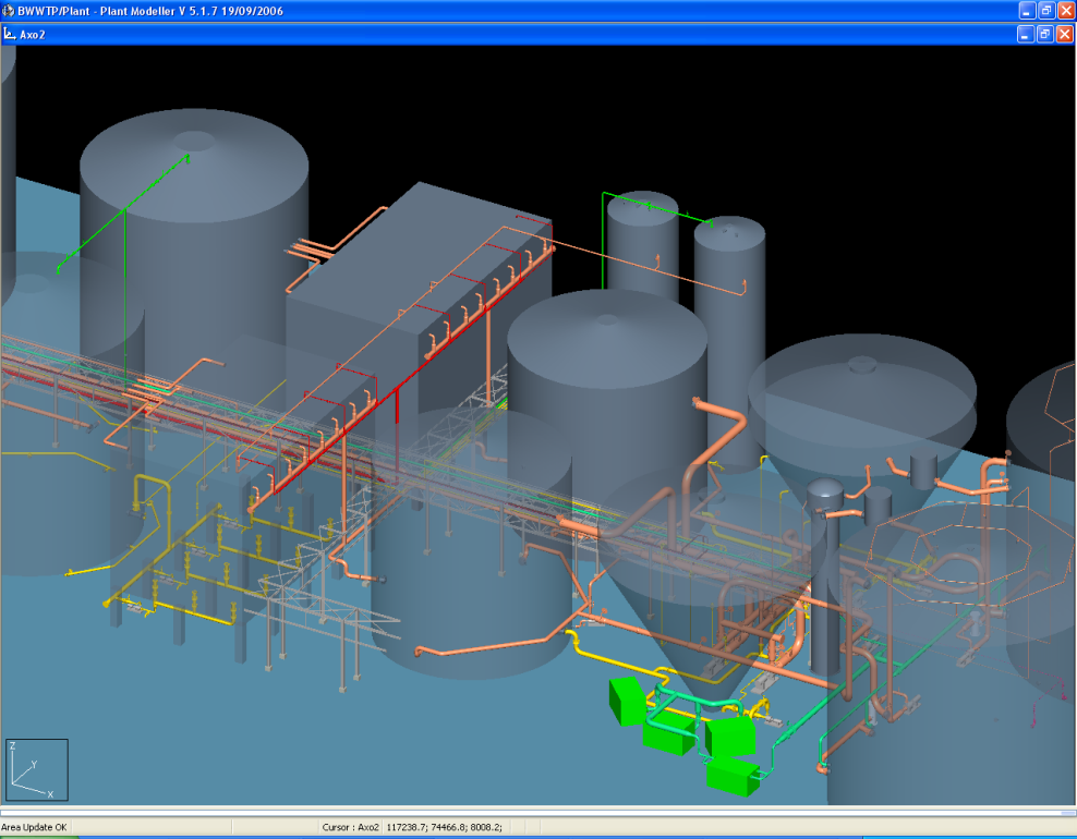
Closer view of Tank Farm Area Piping
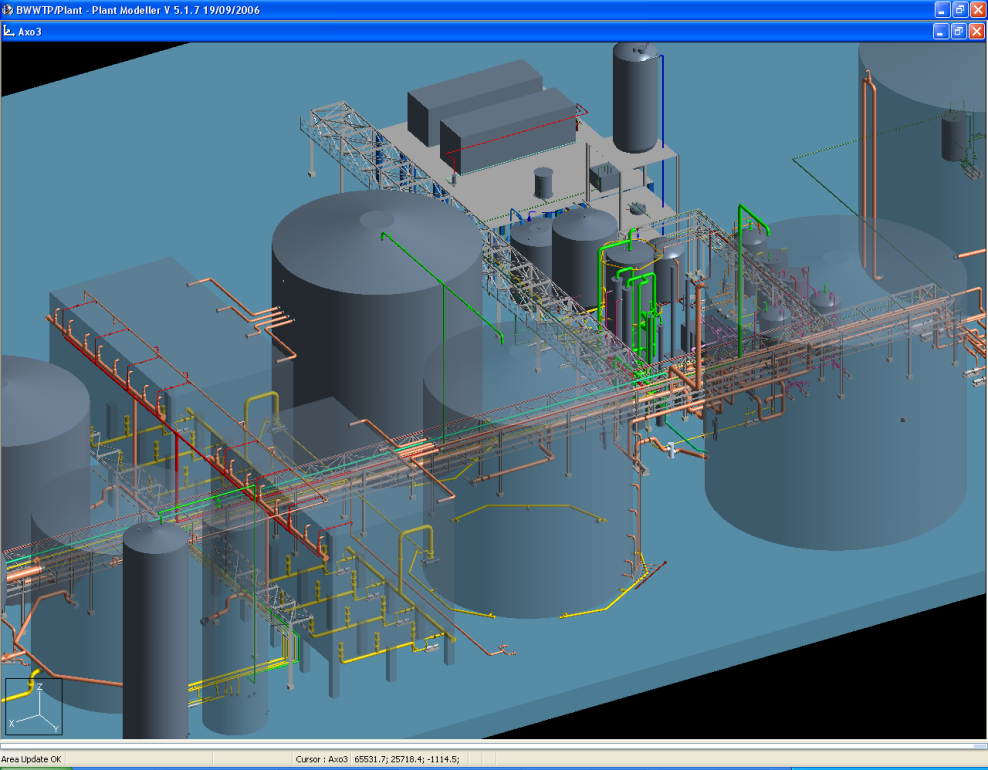
Closer view of Tank Farm Area Piping
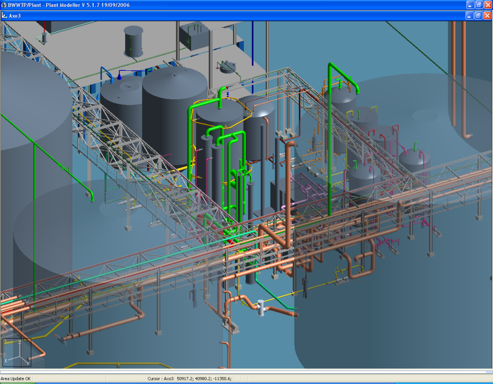
Closer view of Tank Farm Area Piping
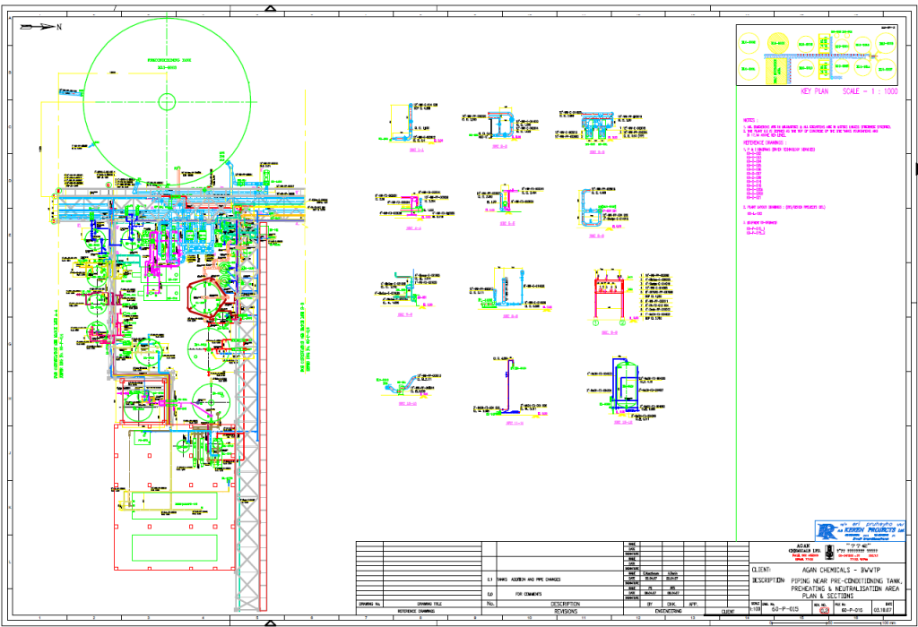
Piping Layout Drawing generated using 3D Plant Design software
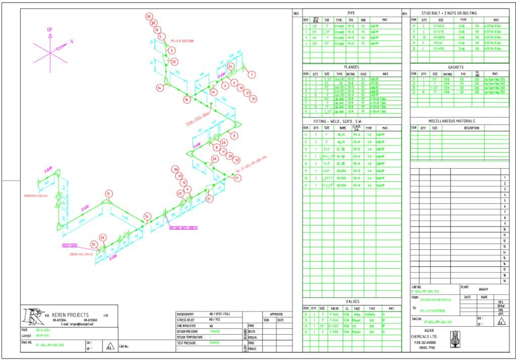
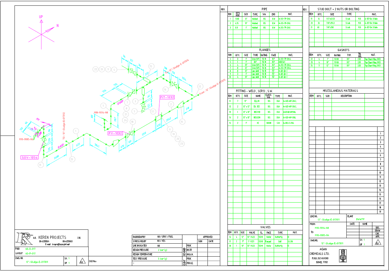
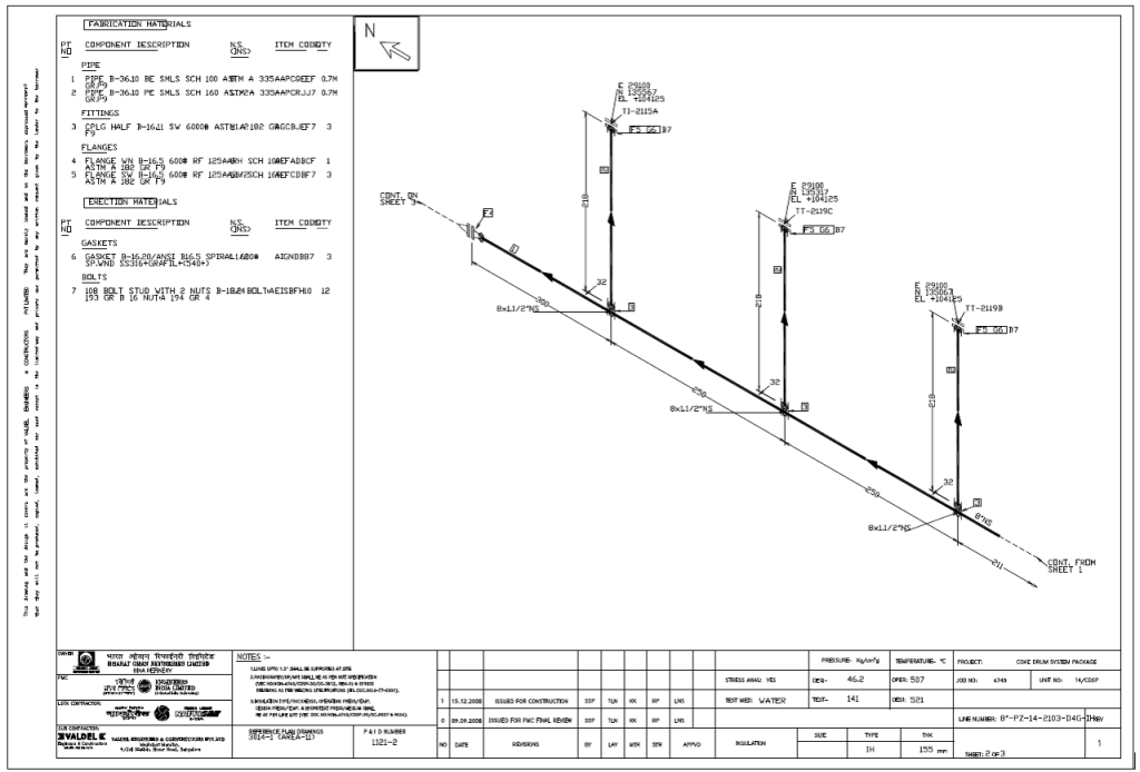
Customized Isometric with BOM generated using 3D Plant Design software
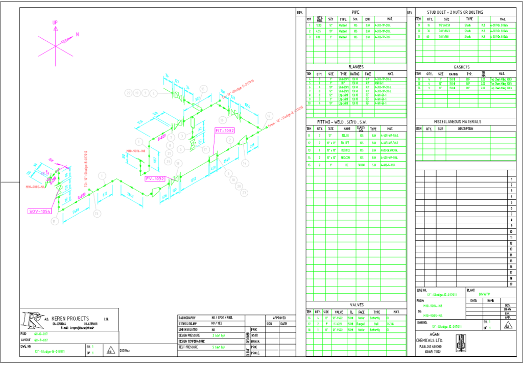
Customized Isometric with BOM generated using 3D Plant Design software
-
Point Cloud to Intelligent 3D Model conversion for a “brown-field” Operating Plant
3D Design of a 220 KVA Substation
Customization and Automation performed on 3D Plant Design software